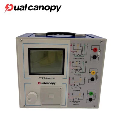
The transformer ratio tester is a very crucial testing device in the power system, transformer manufacturing plants, and maintenance departments. Its core function is to measure the voltage ratio (ratio) of transformers (and transformers with mutual inductance), ratio error, and connection group designation.
Application scope of transformer ratio tester
The transformer ratio tester is applied throughout the entire life cycle of the transformer: manufacturing, installation, maintenance and fault diagnosis.
Power transformer
Three-phase transformer: Measure the transformation ratios for all common connection groups such as Yyn0, Yd11, and Dyn11.
Single-phase transformer: Measure the transformation ratio and polarity of the single-phase transformer.
Tap changer test: Test the transformation ratio of the on-load tap changer (OLTC) of the transformer at different tap positions, and check whether the tap changer switching is accurate and the contacts are in good condition.
2. Special Transformers
Rectifier Transformer: Rectifier transformers used in industries such as electrolysis and electroplating usually have phase-shifting functions. The ratio tester can be used to verify their phase-shifting angles and voltage transformation relationships.
Grounding Transformer: Used to measure the transformation ratio of the Z-type grounding transformer and verify its ability to provide a neutral point connection.
Electric furnace transformer: A high-current transformer used to measure the ratio on the low-voltage high-current side.
Transformer Ratio Tester
3. Transformer
Voltage Transformer (PT, Potential Transformer): Measures the transformation ratio and polarity of electromagnetic voltage transformers.
Current Transformer (CT): Some high-end ratio testers (or ratio testers with CT testing function) can be used to measure the ratio of current transformers.
4. Production and Maintenance Scenarios
New installation acceptance: After the transformer is installed, verify whether the winding turns ratio meets the design requirements, and check if the windings have shifted or short-circuited during transportation.
Preventive test: During regular maintenance, check whether there are inter-turn short circuits, open circuits or poor contact in the windings (because inter-turn short circuits can cause changes in the transformation ratio).
Post-repair testing: After the transformer is disassembled for overhaul, and the windings are replaced or rewound, a voltage ratio test must be conducted to verify the quality of the repair.
Fault Diagnosis: When the transformer differential protection activates or when an internal fault is suspected, the winding condition can be determined through the ratio test.
Transformer Ratio Tester Test Procedure and Judgment Criteria
When using the transformer ratio tester, the following specific test procedures are usually followed:
Measurement principle: Usually, the low-voltage short-circuit method or high-voltage boosting method (or vice versa) is adopted. The transformation ratio is calculated by measuring the induced voltage (or current) on the high-voltage side and the low-voltage side. Modern instruments mostly use the variable bridge method or digital sampling calculation method.
Accuracy requirements: The accuracy of the instrument itself is typically specified as 0.1 class (with an error of ±0.1%) or higher (0.05 class).
Criteria for qualification determination (refer to GB 50150/DL/T 596):
Rated tap position: The allowable deviation of the transformation ratio compared to the data on the manufacturer's nameplate is usually ±0.5% (for specific transformers, such as voltage transformers, the requirements may be stricter).
Other considerations: The transformation ratio should be within 1/10 of the marked data in terms of the impedance voltage value (%), but generally, a ±0.5% or slightly more lenient standard is also referred to, and it must comply with the pattern of the change in the tap position (linear or non-linear).
Three-phase imbalance: For three-phase transformers, the difference in transformation ratios between each phase should generally not exceed 0.5%.
Connection group designation: The connection group designation displayed by the instrument must be exactly the same as the nameplate (such as Yyn0).