Dual Canopy Mechanic Electrical Engineering Co., Ltd. is one of the leading manufacturers and suppliers of lightning arrestor tester in China. Please feel free to wholesale discount products for sale here and get quotation from our factory. Customized orders are welcome.
What is an On-site MOA Live Testing Leakage Current Analyzer?

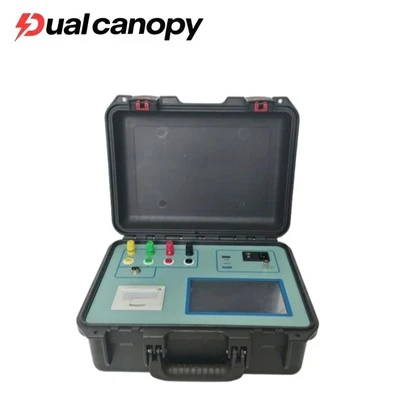
On-Site MOA Leakage Current Analyzer
This portable system checks the health of zinc oxide surge arresters without taking them out of service. Where conventional offline methods require a bus shutdown, the live analyzer measures leakage current directly under operating voltage at power frequency. It separates the fundamental peak resistive component (Ir1p) from harmonic content while the line stays energized, giving operators a real-time view of arrester condition across the transmission network.
What are the Benefits of Live MOA Leakage Current Analysis?
Zero Substation Downtime: Eliminates the need for power outages and switching operations, saving utilities tens of thousands of dollars in downtime costs during routine maintenance.
Real-Time Working Condition Assessment: Measures arrester degradation under true operating voltage and ambient environmental conditions rather than artificial laboratory low-voltage test signals.
Automatic Inter-Phase Interference Evaluation: Incorporates intelligent mathematical algorithms that evaluate and compensate for electromagnetic coupling from adjacent phases in compact switchyards.
High Operator Safety: Equipped with isolated aviation sockets, fuse-protected potential transformer leads, and wireless Bluetooth operation to keep testing personnel at a safe working distance.
Instant On-Site Documentation: Generates immediate graphical waveform displays on a sunlight-readable touchscreen and prints verifiable thermal test receipts for substation maintenance logs.
What are the Different Measurement Methods in Live MOA Testing?
Field technicians using Dual Canopy testing equipment can select from two primary operational wiring methods depending on substation accessibility:
Wired PT Secondary Measurement Method: Connects the instrument's voltage input terminal to the secondary voltage winding of the substation's potential transformer (PT). This provides a precise phase reference to compute the exact power factor angle (Φ), resistive peak current (Ir1p = Ix1p sinΦ), and capacitive peak current (Ic1p = Ix1p cosΦ).
Non-PT Current-Only Measurement Method: Designed for situations where PT secondary terminals are inaccessible or physically remote. This method connects only the current signal leads to the MOA ground strap, using internal harmonic modeling to estimate resistive leakage current without requiring a direct voltage reference cable.
What are the Key Application Scenarios for Substation MOA Analyzers?
110kV / 220kV / 500kV AC Substation Inspection: Conducting live periodic inspections of surge arresters protecting power transformers, circuit breakers, and busbars.
Post-Lightning Storm Diagnostic Audits: Verifying whether surge arresters have suffered micro-cracking or thermal stress after absorbing high-energy transient lightning strikes.
Transmission Line Ground-Lead Monitoring: Evaluating arresters installed along critical high-voltage overhead transmission corridors to prevent line lockouts.
Aging Trend Analysis for Utility Asset Management: Tracking resistive leakage current growth over consecutive years to predict varistor end-of-life and schedule replacement prior to insulation failure.
Performance Parameters for Field Leakage Current Measurement
| Diagnostic Parameter | Performance Indicator | Field Application Context |
|---|---|---|
| Resistive Peak Formula | Ir1p = Ix1p · sinΦ | Fundamental peak resistive leakage current |
| Capacitive Peak Formula | Ic1p = Ix1p · cosΦ | Fundamental peak capacitive leakage current |
| Phase Angle (Φ) Evaluation | ≥ 88° (Excellent / Ideal) | No inter-phase interference |
| Phase Angle (Φ) - Good | 80° to 87.99° | Normal field condition in switchyards |
| Phase Angle (Φ) - Medium | 77° to 79.99° | Moderate electromagnetic interference present |
| Phase Angle (Φ) - Poor | 0 to 74.99° | Check wiring, grounding, or severe interference |
Field-Ready Construction & Ergonomic Hardware Craftsmanship
Designed specifically for rugged outdoor field work, the analyzer weighs only 4.5 KG and features an ergonomic carrying handle integrated into an impact-resistant structural enclosure. Its 7-inch color LCD display is engineered with high-brightness backlighting to ensure readability even under glaring midday sun in open switchyards. Standard equipment includes 10-meter reinforced shielded measurement cables with heavy-duty alligator clips designed to clamp securely onto corroded grounding conductors.
How to Wire and Safely Operate the Analyzer on Site?
Step-by-Step Wiring Protocol: First, connect the instrument's grounding terminal to the substation earth grid using a short, low-resistance cable. For three-phase live testing, attach the Yellow (A), Green (B), and Red (C) current alligator clips to the respective lower grounding leads of the MOAs. Connect the voltage test lead to the PT secondary terminal using the 100mA fuse-protected cables.
Parameter Configuration: On the main menu, select "Three-Phase Test" or "Single-Phase Test". Input the correct PT ratio (Ku) so the instrument correctly calculates primary bus voltage. Press "Test" and observe the waveform stabilization screen.
Safety Rules for Substation Operators: Maintain standard high-voltage safety clearances at all times. Never route test extension cords near high-voltage drop leads. When testing is complete, press "Lock Screen" to freeze data before turning off the power and removing clips in reverse order (voltage leads first, current leads second, earth ground last).

FAQ
Q1: Why is live testing preferred over power-outage testing for surge arresters?
Answer: Live testing allows continuous monitoring under actual electrical operating pressure without interrupting grid service. It identifies active leakage current trends that might not be apparent when the arrester is cold and unenergized.
Q2: What causes inter-phase interference during three-phase live testing?
Answer: In compact switchyards, stray capacitance between Phase A, Phase B, and Phase C conductors causes capacitive currents to leak across phases, which can shift the measured phase angle (Φ). Our analyzer's software provides phase angle evaluation ratings to help operators interpret this effect correctly.
Q3: Can I perform a test if the substation PT secondary voltage is not accessible?
Answer: Yes. You can switch the instrument to the "Non-PT Measurement Method", which relies solely on current signal waveform acquisition and harmonic analysis to determine arrester condition.
Hot Tags: lightning arrestor tester, China lightning arrestor tester manufacturers, suppliers, factory, SF6 AC HI POT TESTER, sf6 analyzer, sf6 test equipment, sf6 test gas, SF6 Testing, sf6 Type in transformers