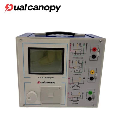
In power transformers, the On-Load Tap Changer (OLTC) is the only component involving mechanical movement and is also one of the components with a relatively high failure rate. Operational statistics indicate that a significant portion of transformer failures are caused by OLTCs. Therefore, conducting regular condition monitoring of OLTCs-to promptly detect issues such as internal contact erosion, abnormal transition resistance, or non-compliant switching times-is crucial for ensuring the safe and stable operation of transformers.
This article provides a detailed analysis of the working principles, key parameters, testing methods, and practical fault-diagnosis applications of transformer OLTC testers, helping power industry technicians gain a deep understanding of the technical essentials and field application value of this testing process.
I. What is an On-Load Tap Changer, and why test it?
An On-Load Tap Changer (OLTC) is a device installed on a transformer that adjusts the output voltage by changing the winding tap position while the transformer is operating under load. Unlike off-circuit (or no-load) tap changers, OLTCs can adjust voltage without interrupting the power supply, making them widely used in modern power grids.
The core operating principle of an OLTC involves using a transition resistor (or transition reactor) to achieve a smooth transition between tap positions during the switching process. This ensures that the current is not interrupted and that no excessive circulating currents are generated. The entire switching operation is completed within a very short timeframe through a sequence of precisely coordinated mechanical actions.
Because the OLTC is a mechanical-electrical hybrid component subject to frequent operation, it faces numerous issues during long-term service: contacts may wear or erode due to repeated switching; transition resistors may experience resistance changes or even breakage due to overheating; and switching mechanisms may suffer from synchronization issues or excessive switching times. If these faults are not detected in time, the consequences range from compromised voltage regulation quality to severe accidents involving transformer burnout.
Therefore, using professional testing instruments to quantitatively measure the operational characteristics of the OLTC is a vital method for assessing its health and detecting potential defects early.
II. Basic Principles of On-Load Tap Changer Testing
The core testing principle of a transformer on-load tap changer (OLTC) tester involves monitoring current or voltage fluctuations during the tap-changing process to capture dynamic characteristics and analyze the switch's operational performance.
During testing, a stable DC test current is typically injected into the contact circuit of the tap changer. When the tap changer performs a switching operation, the contacts undergo a continuous sequence of "make-transition-break." Throughout this process, the insertion and removal of transition resistors cause corresponding fluctuations in the circuit's current (or voltage).
The tester employs high-speed sampling technology to continuously record the waveform of these dynamic changes. By analyzing the waveform, key timing parameters-such as transition time and total switching time-can be precisely measured. Additionally, the system can detect anomalies such as current interruption (where the circuit current momentarily drops to zero) during the switching process.
Modern OLTC testers generally utilize high-speed data acquisition and digital waveform processing technologies. With high sampling frequencies, they can accurately capture switching details at the millisecond or even microsecond level. Upon completion of the test, the instrument automatically plots the switching waveform and calculates relevant parameters; operators can then assess the tap changer's operational status by analyzing the waveform and data.
III. Analysis of Key Test Parameters
When using a transformer OLTC tester, particular attention should be paid to the following key parameters:
1. Transition Time
Transition time refers to the duration during the switching process when the transition resistor is connected to the circuit. This is one of the most critical parameters for evaluating the operational performance of an on-load tap changer. Both excessively long and excessively short transition times are abnormal: an excessively long time may cause the transition resistor to overheat and fail, while an excessively short time may induce significant circulating currents. The transition time must comply with the standard values specified by the tap changer manufacturer.
2. Switching Time
Switching time refers to the total time required to complete the transition from one tap position to the next. It reflects the speed and coordination of the switching mechanism's operation.
3. Transition Waveform (Switching Waveform)
By analyzing the waveform curve of the switching process, one can visually determine whether the switching process is smooth and continuous, whether the operation of the various contacts is properly coordinated, and whether any current interruption occurs. The waveform serves as a crucial basis for evaluating the operational quality of the tap changer.
4. Three-phase synchronism
For three-phase tap changers, the operation of the contacts across the three phases should be essentially synchronous. A lack of synchronism (i.e., poor simultaneity) suggests a potential mechanical fault in the switching mechanism. Three-phase synchronism is a key indicator for assessing three-phase tap changers.
5. Transition resistance value
The transition resistor is a critical component of an on-load tap changer. Testing allows for the calculation or assessment of whether the transition resistance value is normal and whether issues such as resistance drift or breakage exist.
6. Continuity of current
During a normal switching operation, the circuit current should remain continuous; there should be no momentary interruptions dropping to zero. Any interruption in current indicates a serious contact issue and serves as a vital criterion for fault diagnosis.
IV. Common testing methods and operational essentials
In practice, testing an on-load tap changer generally follows this workflow:
First, pre-test preparation. Reliably ground and fully discharge the transformer under test, disconnect external connections, and ensure operational safety. Additionally, verify the tap changer's model, number of taps, and manufacturer-specified standard parameters to prepare for subsequent measurements and data comparison.
Next, correct wiring. Connect the test leads to the corresponding winding terminals of the tap changer in accordance with the instrument's manual. For three-phase testing, ensure correct phase-sequence connections and good contact.
Then, perform the test. Use the transformer's tap changer operating mechanism (electric or manual) to drive the tap changer to switch positions (stepping up or down). Simultaneously, the tester automatically captures and records waveform data for the entire switching process.
Finally, data analysis. After testing, read parameters such as transition time, total switching time, and three-phase synchronism displayed by the instrument. Examine the switching waveforms, compare them against standard values, and assess the device's condition.
In practice, measurements are typically taken at every tap position to comprehensively evaluate the performance of each switching operation and detect potential issues at specific tap positions.
V. Application of Testing in Transformer Fault Diagnosis
On-load tap-changer (OLTC) testing plays a pivotal role in transformer condition assessment because it quantitatively reflects the health of internal mechanical and electrical components-parts that cannot be evaluated through visual inspection alone.
Detecting contact ablation and wear: Contacts gradually wear down and suffer ablation during prolonged, repetitive switching operations, leading to increased contact resistance. Such issues often manifest in switching waveforms and transition times, allowing for timely detection through testing.
Assessing transition resistor anomalies: Changes in resistance due to overheating, or even resistor breakage, directly affect the current waveform during the switching process. Analyzing the waveform makes it possible to determine whether the transition resistor is functioning correctly.
Detecting current interruption faults: Current interruption during switching indicates severe contact issues and can lead to serious consequences such as arcing or burn damage. Testing instruments can precisely capture these interruptions, providing direct evidence for troubleshooting.
Evaluating mechanism operation: Measuring switching time and three-phase synchronization allows for the assessment of the switching mechanism's mechanical coordination, helping to identify faults such as jamming or lack of synchronization.
Comprehensive diagnosis: In practice, OLTC testing is typically combined with other methods-such as DC resistance testing, dissolved gas analysis (DGA) of the oil (specifically from the tap-changer oil compartment), and transformer turns ratio testing-to form a comprehensive assessment. Cross-referencing multiple methods is essential for an accurate and holistic evaluation of the tap-changer's condition.
It is important to note that comparative analysis is crucial when interpreting test data. On one hand, measured time parameters should be compared against the manufacturer's standard values. On the other hand, current data should be compared with historical records to observe trends, while horizontal comparisons-between phases and across different tap positions-help identify anomalies.
VI. Precautions for Testing
To ensure the accuracy of test results and operational safety, the following points must be observed during on-site testing:
First, before testing, ensure the transformer has been fully discharged and reliably grounded, and that all external connections are disconnected to guarantee the safety of personnel and equipment.
Second, ensure all wiring connections are secure and provide good contact; poor contact can compromise the accuracy of the measured waveforms. Third, the operation of the tap changer must strictly adhere to established procedures, ensuring that the switching action is fully completed.
Fourth, every tap position must be tested individually to avoid overlooking any specific position that might harbor a defect.
Fifth, relevant parameters and conditions during testing must be accurately recorded to provide a basis for subsequent data analysis and trend comparison.
In conclusion:
As a vital instrument for specialized transformer testing, the on-load tap changer (OLTC) tester plays an irreplaceable role in condition assessment and fault diagnosis, thanks to its ability to precisely capture the dynamic characteristics of the switching process. A thorough understanding of testing principles, key parameters, and correct operational methods is of great practical significance for power technicians; it enables the timely detection of potential tap changer defects, the prevention of transformer failures, and the assurance of safe power grid operation.
With the growing adoption of condition-based maintenance and advancements in testing technology, OLTC testers are evolving toward high-speed sampling, intelligent analysis, and multi-parameter integration. Selecting an OLTC tester that offers high sampling precision, robust waveform analysis capabilities, and ease of operation will provide more reliable technical support for the safe operation of transformers.