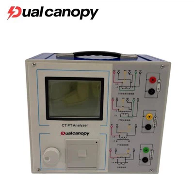
Two weeks ago, while conducting pre-commissioning acceptance tests on a 110kV main transformer that had just undergone a major overhaul, we found that the DC resistance, insulation resistance, and dielectric loss values were all within standard limits; however, the transformer turns ratio tester recorded an error of 0.68% for the Phase B medium-voltage tap-a figure clearly exceeding the permissible engineering limit. Upon dismantling the tap changer, we discovered localized ablation on the Phase B moving contact and slight carbonization marks on the insulating barrier. Had we relied solely on insulation resistance and dielectric loss data, this unit would very likely have been put into service with a latent defect. This case highlights a frequently overlooked fact: while the turns ratio test may appear to simply measure a voltage ratio, it actually verifies the geometric integrity and correct interconnection of the transformer windings-and winding integrity is precisely the foundation upon which the insulation system's ability to withstand long-term electrical, thermal, and mechanical stresses depends.
I. Testing Principles and Engineering Significance: More Than Just "High Voltage Divided by Low Voltage"
Many field personnel simplify the turns ratio test to merely "dividing the high-voltage side voltage by the low-voltage side voltage," interpreting the result simply as a figure like "3.15" or "10.5." While this understanding is mathematically correct, it is far from sufficient in an engineering context. A transformer's rated turns ratio determines not only the voltage transformation relationship but is also directly linked to calculating circulating currents during parallel operation, setting current transformer ratios for protective relaying, and matching voltages for reactive power compensation devices. If the actual turns ratio deviates significantly from the nameplate value, the equipment cannot be safely connected to the power grid, even if its insulation is intact.
Regarding measurement principles, modern transformer turns ratio testers predominantly employ the Voltage Ratio Method: a stable, precise AC excitation voltage (typically a low, safe voltage near power frequency) is applied to the transformer's low-voltage side. Simultaneously, the induced voltage on the high-voltage side is precisely measured; the ratio between the two is calculated and compared against the nameplate rating to determine the error. For three-phase transformers, the instrument must independently measure phases A, B, and C while capturing inter-phase phase relationships to verify the vector group (e.g., Dyn11, Yyn0, Yd11). Consequently, a complete three-phase turns ratio test yields not only three ratio values but also three-phase angle differences, providing a comprehensive verification of the internal lead connections.
It is important to clarify that the "principle" of turns ratio testing encompasses two aspects: first, the electromagnetic induction relationship regarding the number of turns-specifically, U₁/U₂ ≈ N₁/N₂ (under ideal conditions where excitation current and impedance voltage drop are negligible); and second, the principles of error control in engineering measurement. Factors such as the stability of the field excitation source, the synchronous sampling accuracy of measurement channels, and the ability to compensate for minute voltage drops caused by tap-changer contact resistance collectively determine whether the instrument can operate reliably at accuracy levels of 0.1% or even 0.05%. While traditional manual single-phase testing methods rely on the same underlying principles, they struggle to meet modern condition-based maintenance requirements for data repeatability due to issues such as frequent wiring changes, manual reading errors, and inconsistencies across three-phase data. Consequently, the equipment we are launching emphasizes synchronous three-phase excitation and digital phase-locked sampling; the goal is not merely to showcase technical prowess, but to elevate field measurements from reliance on "empirical judgment" to a "data-driven baseline" approach.
From an engineering perspective, the core value of the turns ratio test lies in verifying the geometric integrity of the windings. Following manufacturing, transport, installation, major overhauls, or exposure to short-circuit stresses, windings may undergo axial or radial displacement; inter-turn insulation damage can alter the effective number of turns; or errors may occur in lead connections or tap changer positioning. In the early stages, such changes often do not trigger a significant drop in insulation resistance or immediately generate detectable partial discharge signals; however, they directly alter the effective number of turns, leaving a clear, quantifiable footprint in the turns ratio error. In short, the transformer turns ratio tester serves as the primary screening tool for detecting whether the physical structure of the windings has undergone alteration.
II. Role in Condition Assessment: From "Acceptance Test" to "Trend Baseline"
In traditional preventive testing regimes, the transformer turns ratio test is often classified as a mandatory procedure following the commissioning of new equipment or major overhauls; once completed, the data is simply archived until the next major overhaul. This "point-in-time inspection" model is increasingly being superseded by the "trend monitoring" approach characteristic of Condition-Based Maintenance (CBM). For transformers in service for over a decade, the value of turns ratio data lies not merely in whether the current reading falls within limits, but in whether the slope of the error curve has shifted compared to data from the previous one or five tests.
Analysis of our operations and maintenance database reveals that seemingly "minor deviations" in the turns ratio-such as a gradual rise in error from 0.15% to 0.35% in a specific phase-often signal a loosening of the winding clamping structure or mechanical wear in the tap changer, particularly when accompanied by a simultaneous increase in DC resistance unbalance. Conversely, a sudden spike in turns ratio error (e.g., a jump from 0.2% to 0.6% at a specific tap position) typically points to an acute event: contact ablation in the tap changer, localized deformation caused by a loose and overheating lead connection, or a sudden change in effective turns due to an internal inter-turn short circuit. These two trend patterns-gradual drift versus sudden spikes-dictate vastly different maintenance strategies: the former calls for scheduled maintenance and tap changer servicing, while the latter necessitates an immediate shutdown and inspection.
Consequently, the role of modern transformer turns ratio testers in condition assessment has evolved from simple "reading tools" to "baseline data acquisition terminals." These instruments must not only provide high-precision instantaneous readings but also demonstrate stable measurement repeatability and offer interfaces for automatic comparison with historical data. In the field, we require technicians to record current temperature, tap position, and error values while simultaneously retrieving data from the past three years for the same tap position and temperature-corrected conditions. If the instrument cannot guarantee a repeatability precision of ±0.05%, subtle trend changes will be obscured by measurement noise, rendering the condition assessment meaningless. Furthermore, the turns ratio test is a mandatory and indispensable part of post-incident assessment. When a transformer is subjected to a nearby short circuit, lightning overvoltage, or mechanical impact during transport, internal windings may suffer slight displacement or damage to turn-to-turn insulation, even if there is no visible external damage. In such cases, while insulation resistance and dielectric loss values might remain within permissible limits, the turns ratio test can rapidly detect any changes in the number of effective turns. We recommend that any transformer subjected to severe external impact or a trip caused by protection system operation undergo a full-tap turns ratio test before being returned to service, with the results compared against pre-incident baseline data. This is not an act of excessive caution, but a measure based on fundamental engineering principles regarding the direct link between winding mechanical strength and electromagnetic integrity.
III. Application of Turns Ratio Testing in Transformer Insulation Diagnosis: The Interplay Between Structural Integrity and Insulation Failure
It is necessary to clarify a technical distinction here: a transformer turns ratio tester measures the winding turns ratio and vector group; it does not directly measure the dielectric loss factor (tan δ), insulation resistance, partial discharge magnitude, or dissolved gases in the oil. Therefore, strictly speaking, turns ratio testing falls under the category of "winding structure and connection diagnosis" rather than "insulation medium diagnosis." However, in the actual progression of insulation faults, the two are deeply interconnected and should not be viewed in isolation.
The breakdown of an insulation system rarely occurs in isolation. Consider an inter-turn short circuit: when the insulation paper between specific turns within a winding breaks down due to thermal aging, partial discharge erosion, or mechanical stress, the affected turns are "bypassed" by the short circuit. This reduces the number of turns effectively participating in electromagnetic induction, thereby altering the voltage ratio between the high-voltage and low-voltage sides. In this scenario, the turns ratio tester will detect that the ratio error for the affected phase exceeds permissible limits, while DC resistance measurements may show a decrease in resistance for that phase (as the shorted turns effectively reduce the conductor length). Thus, the abnormal turns ratio serves as direct electrical evidence of structural damage resulting from insulation breakdown.
Consider also a tap changer fault: whether on-load or off-load, the tap changer is located inside the transformer, and its insulation structure comprises insulating oil, paperboard barriers, and the insulation gaps between moving and fixed contacts. When internal discharge, contact ablation, or severe deterioration of the insulating oil occurs, it may not only trigger anomalies in dissolved gas analysis (such as increased acetylene or hydrogen levels) but also lead to incorrect contact positioning, abnormally high contact resistance, or even loose lead connections. These mechanical and electrical changes are directly reflected in the turns ratio data for the corresponding tap position-manifesting as a sudden spike in error, non-smooth transitions between tap positions, or a significant deviation of data in one phase compared to the other two. Therefore, within the insulation diagnostic workflow, the turns ratio test serves as a "structural integrity screen": if the ratio is normal and stable, one can largely rule out major changes in the number of turns or severe connection errors; if the ratio is abnormal, immediate follow-up-combining dielectric loss testing, partial discharge detection, frequency response analysis (FRA), and dissolved gas analysis (DGA)-is required to pinpoint whether the fault stems from winding deformation, inter-turn insulation breakdown, or a combined mechanical and insulation failure of the tap-changer system.
This synergistic relationship is particularly critical for transformers that have undergone major overhauls. Such overhauls involve operations like core lifting, lead re-soldering, tap-changer maintenance or replacement, and insulation paper repair. Even minor errors at any stage-such as a misconnected lead, misalignment of the tap-changer position, or insufficient axial clamping force during winding reassembly-can lead to serious consequences once the unit is put back into service. In such cases, relying solely on insulation resistance and dielectric loss tests is insufficient, as these tests cannot verify whether the wiring strictly conforms to the design drawings. Only by systematically comparing data across all tap positions and phases using a transformer turns ratio tester can the geometric correctness of the winding connections be confirmed. This effectively serves as the ultimate verification of the "installation integrity" of the entire insulation system.
In short, within the multidimensional diagnostic framework for modern transformers, the turns ratio test forms a complementary matrix alongside dielectric loss, partial discharge, oil analysis, and infrared thermography. The turns ratio test focuses on whether the structure has changed; dielectric loss on whether the insulation medium has aged; partial discharge on the presence of active defects; and oil chromatography on chemical reactions driven by thermal and electrical stress. Omitting any of these dimensions could leave blind spots in the diagnostic conclusions.
IV. Analysis of Core Parameters: Interpreting the Tester's Data
When using a transformer turns ratio tester, the values displayed on the screen-such as "3.215" or "0.8%"-represent more than just simple numbers. Understanding the physical significance and engineering limits of each parameter is a prerequisite for accurate diagnosis.
Turns Ratio (Ratio / k): For a two-winding transformer, this is typically expressed as the ratio of the high-voltage side rated voltage to the low-voltage side rated voltage, or calculated directly as the ratio of the number of turns. During on-site measurements, the instrument directly calculates the actual turns ratio based on the applied excitation voltage and the measured response voltage. For three-phase equipment, the actual turns ratio for phases A, B, and C must be recorded individually, and the average value across the three phases calculated. The variation between phases is itself a critical indicator; in an ideally symmetrical structure, the turns ratios of the three phases should be highly consistent. If one phase exhibits a systematic deviation from the other two, it warrants attention, even if the error for each individual phase remains within absolute limits.
Turns Ratio Error (Error %): This is the primary metric for determining compliance. The calculation formula is:
Error = (Measured Turns Ratio - Rated Turns Ratio) / Rated Turns Ratio × 100%
In accordance with DL/T 596 "Code for Preventive Test of Electric Power Equipment" and standard engineering practices, the turns ratio error for each phase of a power transformer should generally be kept within **±0.5%**; stricter requirements (e.g., ±0.2%) may apply to precision metering or special-purpose transformers. The average error across the three phases is usually required to be even lower. It is important to emphasize that error assessment must be based on the rated tap position specified on the equipment nameplate; data from different tap positions must not be conflated. A common error encountered on-site is operators calculating errors using default nameplate values without verifying the actual tap changer position, leading to incorrect assessments.
Connection Group (Vector Group): For example, "Dyn11" indicates a delta (D) connection on the high-voltage side and a star (y) connection with a brought-out neutral (n) on the low-voltage side, with the high-voltage line voltage leading the low-voltage line voltage by 30 degrees (corresponding to the 11 o'clock position). The turns ratio tester automatically determines or verifies the connection group by measuring the phase relationship between the high-voltage and low-voltage windings. An incorrect connection group indicates an error in the internal lead connection sequence-a high-risk issue during reconnection following a major overhaul. Instruments equipped with automatic group identification capabilities can significantly reduce errors caused by human misjudgment.
Tap Position Data: For on-load or off-load tap-changing transformers, turns ratio testing should cover all operational tap positions (or, at a minimum, the frequently used and extreme tap positions). Each tap position should have its own record of transformation ratios and error values. Under healthy conditions, the variation in transformation ratios across tap positions should follow a smooth, continuous, step-like pattern. A sudden jump in data compared to adjacent taps, or an error value significantly higher than that of other taps, typically indicates poor contact at the tap changer contacts, abnormal transition resistance, or mechanical stress concentration on internal leads specific to that tap position.
Phase Difference and Angular Relationship (Phase Angle / Clock Number): During simultaneous three-phase testing, the instrument outputs not only the ratio but also the phase angle difference between the high-voltage and low-voltage sides. For standard vector groups, this angle must correspond strictly to expected values (e.g., multiples of 30°, 0°, or -30°). Phase angle anomalies are usually directly linked to crossed leads or internal winding connection errors; they serve as a more sensitive detector for wiring faults than transformation ratio errors alone.
DC Resistance Correlation: Although DC resistance is measured using specialized equipment, data for the corresponding phase's DC resistance must be retrieved immediately if a transformation ratio anomaly is detected. If an increase in ratio error is accompanied by a decrease in DC resistance, the likelihood of an inter-turn short circuit is very high; if both the ratio error and DC resistance increase, it may indicate poor contact or broken strands in the leads. In our field procedures, the transformation ratio test and DC resistance test are bundled into a "combined screening package" for post-overhaul commissioning.
Repeatability and Environmental Records: A high-quality test report should contain more than just electrical parameters; it must also include the ambient temperature, oil temperature (if applicable), humidity, test time, operator details, and instrument serial number. Temperature has a slight effect on winding resistance and induced voltage; while the transformation ratio is fundamentally a turns ratio (minimally affected by temperature), the stability of the excitation source and thermal drift in the measurement circuitry can impact high-precision readings. Therefore, maintaining standardized records of the testing environment is essential for ensuring the comparability of trend data over the years.
V. Application Scenarios and Equipment Selection: Bringing Laboratory-Grade Precision to the Substation Site
The launch of this transformer turns ratio tester represents more than just the provision of a measurement circuit; it offers field engineering teams a comprehensive solution capable of operating in complex electromagnetic environments, facilitating rapid connection, and integrating seamlessly with operations and maintenance platforms. The following section outlines how to effectively apply technical specifications in practice, covering both application scenarios and key selection criteria.
Core Application Scenarios:
1. Commissioning Acceptance for New Equipment: This represents the most rigorous scenario for turns-ratio testing. Before a newly installed transformer is energized for the first time, a full-tap, three-phase turns-ratio test must be performed, and the results compared item-by-item against the manufacturer's factory test report. Any discrepancy exceeding ±0.2% requires a written explanation from the manufacturer or the installation contractor. This serves as the final line of defense against incidents where equipment passes factory tests but suffers from incorrect on-site wiring.
2. Post-Overhaul Commissioning Verification: As mentioned in the introduction, major overhauls involve the reassembly of windings, leads, and switches. We recommend a "three-step verification" process: Step 1: Record the baseline turns-ratio before untanking the core (if conditions permit); Step 2: Conduct a preliminary turns-ratio check after reassembly but before oil filling (low-voltage excitation tests can be performed in the dry state); Step 3: Perform precise full-tap measurements after oil filling and settling, but prior to official energization, and compare these against the baseline.
3. Annual Condition-Based Maintenance Surveys and Trend Monitoring: For critical transformers in service (such as main transformers at hub substations or dedicated transformers for major industrial users), we recommend performing full-tap turns-ratio tests every 1–3 years, with data entered directly into the condition assessment database. If the error curve shows a sustained upward trend, maintenance on the tap changer or further diagnostic testing should be scheduled proactively, even if the values remain within limits.
4. Retesting After Fault-Induced Tripping: For any tripping event caused by differential protection, Buchholz (gas) protection, or external short circuits, a turns-ratio test must be a mandatory re-inspection item before the transformer is returned to service. This is not merely a formality; it is a direct method to verify whether the internal windings have undergone permanent geometric deformation due to short-circuit electromagnetic forces.
5. Verification After Specialized Tap Changer Maintenance: Following any maintenance, contact replacement, or insulating oil treatment involving an on-load tap changer, the turns ratio for the affected tap positions must be verified to ensure complete alignment between mechanical positioning and electrical connection. Key Considerations for On-Site Selection and Technical Matching:
6. Simultaneous Three-Phase Measurement Capability:** Traditional single-phase, phase-by-phase testing requires repeated rewiring; this is not only time-consuming (often taking over 30 minutes for a single three-phase transformer) but also prone to wiring errors during frequent disconnection and reconnection. Modern transformer turns-ratio testers should support a single three-phase connection setup, automatic sequential measurement, and the simultaneous on-screen display of comparative data for all three phases. This not only boosts efficiency but, more importantly, minimizes the impact of human wiring errors on data integrity.
7. Test Accuracy and Resolution: For condition assessment purposes, the instrument's basic accuracy should be 0.1% or better, with a resolution of 0.01%. If the instrument's inherent repeatability error approaches 0.2%, it becomes impossible to detect genuine, subtle trend changes. When selecting equipment, focus on manufacturer-provided repeatability test reports rather than just the nominal "peak accuracy" figure.
8. Interference Immunity and On-Site Adaptability: Substations generate strong electromagnetic fields, particularly near high-voltage busbars or GIS feeder bays. Instruments require robust electromagnetic shielding, digital filtering algorithms, and stable excitation sources capable of resisting interference. We recommend models that automatically adjust excitation levels and extend integration times in noisy environments to improve the signal-to-noise ratio, rather than simply relying on "increasing excitation voltage" to mask interference issues.
9. Full-Tap-Position Scanning Functionality: For transformers equipped with multi-position tap changers, manual switching and data recording are highly error-prone. The instrument should support preset tap ranges, provide automatic prompts for switching, record turns-ratio and error data for each tap, and generate a comprehensive report covering all positions. This feature saves significant time during post-overhaul verification and routine condition surveys while reducing the risk of missed measurements.
10. Data Management and Platform Integration: The instrument should possess sufficient memory to store multiple test records (including equipment ID, tap position, three-phase data, ambient temperature, and test time) and support data export to standard formats (such as CSV or PDF reports) via USB, Bluetooth, or dedicated data cables. Direct integration with corporate asset management platforms is becoming a fundamental requirement for modern O&M systems, rather than merely an optional feature. Safety Design and Operational Protection: Testing involves induced voltage on the high-voltage side (even though the excitation source is on the low-voltage side, dangerous voltages can be induced on the high-voltage side, particularly in equipment with high transformation ratios). The instrument must feature over-voltage protection, over-current protection, automatic discharge functions, and clear indications of connection status. Field operators must strictly adhere to the sequence of "connect ground first, then signal leads; disconnect signal leads first, then ground," and the instrument's safety interlock design should facilitate rather than hinder this workflow.
Connection Flexibility and Adapters: Transformer terminal layouts vary significantly across different voltage ratings and vector groups. The instrument should be equipped with a variety of standard test clips, extension cables, and adapters to ensure safe and secure connections, even in confined spaces like transformer terminal boxes or near bushings. Connection reliability directly determines measurement repeatability; test clips with unstable contact resistance introduce random errors that can mask actual changes in the equipment's condition.
VI. Common Misconceptions and Corrections in Field Practice
During the widespread adoption of transformer turns-ratio testers, we have identified several typical misconceptions in the field that require repeated emphasis during technical training.
Misconception 1: Testing only one tap position or one phase. To save time, some field operations test only the phase corresponding to the commonly used tap position, or test only the high-to-low voltage ratio while ignoring the medium-voltage winding. For three-winding transformers (e.g., 220/110/35 kV), the turns-ratio relationship between every pair of windings must be verified; because windings at different voltage levels have distinct insulation structures and mechanical constraints, a fault might occur in only one specific winding pair.
Misconception 2: Neglecting vector group verification. Some operators focus solely on whether the turns-ratio error falls within ±0.5%, without checking if the vector group displayed by the instrument matches the nameplate. An incorrect vector group connection (e.g., connecting a Dyn11 unit as Dyn1) might still yield turns-ratio values within the acceptable error range (depending on specific phase relationships), yet it would cause catastrophic circulating currents during parallel operation. Therefore, vector group verification is just as critical as assessing turns-ratio error.
Misconception 3: Failing to record environmental and tap position information. Data lacking tap-position records cannot be compared with historical data, while data lacking temperature records makes it impossible to determine whether measurement conditions were consistent. We require that on-site test reports include five essential pieces of information-photos of the equipment nameplate, tap-changer position indication, ambient temperature, test time, and instrument serial number-with no omissions allowed.
Misconception 4: Equating an abnormal turns ratio directly with "insulation damage." As previously mentioned, an abnormal turns ratio reflects changes in winding structure or connections; the root cause could be mechanical displacement, wiring errors, or switch malfunctions, or it could be an inter-turn short circuit (a consequence of insulation failure). The correct diagnostic process should be: abnormal turns ratio → comprehensive assessment combining DC resistance, frequency response analysis, partial discharge, and dissolved gas analysis (DGA) → identification of the specific fault type (mechanical, connection-related, or structural damage caused by insulation failure) → formulation of a maintenance strategy. Jumping straight to the conclusion that "the insulation is damaged" is unprofessional and may mislead the direction of maintenance efforts.
Conclusion: The Irreplaceability of Fundamental Tests
In an era where diagnostic technologies for power equipment are becoming increasingly complex, advanced methods such as partial discharge detection, frequency response analysis, infrared thermography, and dissolved gas analysis (DGA) are constantly emerging. Nevertheless, the turns ratio and vector group tests performed by transformer turns ratio testers remain fundamental to all these advanced diagnostic
definitive "structural baseline." Without an accurate turns-ratio baseline, the reference curve for frequency response analysis lacks geometric significance; without verification of the correct vector group, safety conditions for parallel operation cannot be confirmed; and without confirming the integrity of the windings, placing a unit back into service after insulation repairs entails latent risks.
We are launching this device not to replace existing diagnostic technologies, but to reinforce the most fundamental and indispensable inspection step: verifying that the transformer's winding geometry and electrical connections align perfectly with design blueprints, historical data, and operational requirements. Within a condition-based maintenance framework, this "consistency verification" serves as the technical cornerstone for shifting from reactive emergency repairs to proactive prevention.
For operations and maintenance organizations, the value of investing in a high-precision, highly repeatable transformer turns-ratio tester-one that supports data management-lies not in the instrument's price tag. Rather, its value stems from providing a source of structural integrity data for the entire transformer asset base-data that allows for long-term tracking, cross-unit comparisons, and direct correlation with protection settings. As we move into 2026-a time characterized by aging grid infrastructure, compressed maintenance windows, and ever-increasing demands for operational reliability-the value of such fundamental data will only grow in importance rather than being marginalized.