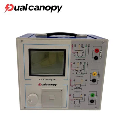
The withstand voltage test for 35kV cables mainly adopts the AC withstand voltage test, as its frequency is the same or similar to the industrial frequency (50Hz), which can most realistically simulate the voltage conditions during operation. This is the most effective method for testing the insulation performance of cables. DC withstand voltage tests are no longer recommended for cross-linked polyethylene (XLPE) insulated cables, as it is prone to generating space charges in the insulation layer, which can cause damage to the insulation and the test results are poor.
The following are the core equipment used for the 35kV cable AC withstand voltage test:
Series resonance AC withstand voltage test equipment (commonly used)
Working principle: By forming a series resonance with the tested cable (capacitive load) using an inductor, a high voltage is generated on the test sample. The power supply only needs to provide the active power of the system losses, thus significantly reducing the required power supply capacity. The size and weight of the equipment can also be optimized.
System composition:
Frequency conversion power supply: Converts the alternating current power supply into a power supply with adjustable frequency (usually 30-300Hz), which is used to adjust the system to reach the resonant state.
Boost Transformer: Increases the output voltage of the frequency conversion power supply to provide sufficient energy for the resonant circuit.
Inductor: The core component. At specific frequencies, its inductance and the capacitance of the cable resonate. It is usually in a multi-section form and is combined in series and parallel to match the capacitance of different lengths of cables.
Cable AC withstand voltage test equipment
Capacitive voltage divider: It is used to accurately measure the high voltage value on the tested cable and serves as an overvoltage protection signal.
Compensation capacitor (optional): If the capacitance of the cable is very small, resulting in an excessively large required inductance of the reactor that is difficult to achieve, this is used to compensate for the capacitance.
Power frequency withstand voltage test transformer (traditional method, less used)
High voltage is directly generated using power frequency test transformers. For 35kV long cables, due to their large capacitance, the capacity of the test transformer needs to be extremely large (up to several thousand kVA), making the equipment extremely heavy and inconvenient to use on-site. Currently, it has been largely replaced by series resonant devices.
0.1Hz ultra-low frequency (VLF) withstand voltage test equipment (can be used as an alternative method)
For 35kV cables with smaller capacity or when resonant equipment is lacking, a 0.1Hz ultra-low frequency withstand voltage device can be used. This device is small in size and light in weight.
Principle: The test is conducted using a 0.1Hz ultra-low frequency sine wave voltage. This type of voltage causes far less damage to insulation compared to direct current, and the equipment capacity requirements are much lower than those for alternating current at the power frequency.
Note: Its test standards are different from those of alternating current at a fixed frequency. The equivalent relationship has specific regulations.
Summary: Currently, on-site tests for 35kV cables involve performing AC withstand voltage tests. The preferred and most commonly used method is the series resonant AC withstand voltage test device.
Test item
The preventive test or acceptance test of cables not only includes the withstand voltage test, but is a set of combined tests. The following is the typical test item process for 35kV cables (taking the most common XLPE cables as an example):
Insulation resistance measurement
Objective: To conduct a preliminary inspection to determine whether the main insulation of the cable and the outer sheath are damp or if there is overall deterioration.
Equipment: Insulation resistance tester (megohmmeter), usually using the 5000V voltage setting.
Main insulation AC withstand voltage test (core item)
Objective: To test the strength of the main insulation of the cable and identify concentrated defects (such as sharp points or air gaps generated during manufacturing or laying), which is a crucial test for determining whether the cable can be put into operation.
Equipment: As mentioned above, the series resonance test system.
Outer sheath pressure resistance test
Objective: For cables with metal sheaths, armored jackets, and outer sheaths, check the integrity of the outer sheath to prevent water from entering the metal sheath.
Equipment: DC withstand voltage tester (usually at 10kV setting) or megohmmeter.
Test Standard Procedure
Mainly based on the power industry standards of the People's Republic of China and the national standards.
GB 50150-2016 "Standard for Electrical Equipment Commissioning Tests in Electrical Installation Engineering"
This is the highest standard for the handover test that must be followed after the cable installation is completed and before it is put into operation.
The main regulations for 35kV cross-linked polyethylene (XLPE) cables:
Main insulation AC withstand voltage test:
Test voltage: 2U₀ (U₀ is the rated voltage between the cable conductor and ground or between the conductor and the metal shielding layer). For 35kV cables, U₀ is typically 21kV. Therefore, the test voltage is 2 × 21 = 52kV.
Test duration: 60 minutes.
Frequency: It is recommended to use an alternating voltage ranging from 20Hz to 300Hz.
Insulation resistance measurement: There is no specific stipulation on the resistance value, but it is required that "the insulation resistance value can be specified by oneself". In practice, it is usually required that the absorption ratio (R60s/R15s) be greater than 1.3, or there should be no significant decrease compared to similar cables or previous data. The value is generally not lower than several gigohms.
DC withstand voltage test for the outer sheath: The test voltage is 10 kV and the duration is 1 minute.
DL/T 596-2021 "Power Equipment Preventive Testing Procedures"
This is the standard that is used for conducting regular preventive tests on the cables during their operation.
The main regulations for 35kV cross-linked polyethylene (XLPE) cables (taking the post-repair test as an example):
Main insulation AC withstand voltage test: It is the same as the commissioning test standard, namely 2U₀, for 60 minutes.
Insulation resistance measurement: It is required that there should be no significant decrease when compared with previous data.
DC withstand voltage test for outer sheath: The test voltage is 6kV and the duration is 1 minute. (Note: The preventive test voltage is lower than the交接 test voltage
GB/T 12706.4-2020 "Power Cables and Accessories with Rated Voltage from 1kV (Um = 1.2kV) to 35kV (Um = 40.5kV), Extruded Insulation Type - Part 4: Test Requirements for Power Cable Accessories with Rated Voltage from 6kV (Um = 7.2kV) to 35kV (Um = 40.5kV)"
This standard mainly covers the type tests for cables and accessories, but the test requirements therein form the basis for developing on-site test procedures.