


Dual Canopy Mechanic Electrical Engineering Co., Ltd. is one of the leading manufacturers and suppliers of fully automatic transformer ratio tester in China. Please feel free to wholesale discount products for sale here and get quotation from our factory. Customized orders are welcome.
What is a Fully Automatic Transformer Ratio Tester?
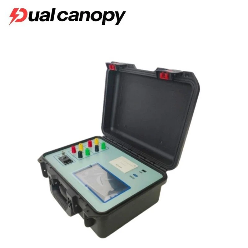
A TTR tester verifies the ratio between primary and secondary windings by injecting a low-voltage signal into one winding and measuring the voltage induced in the other. The turns ratio is the simple quotient of these two readings. This single check confirms winding integrity, tap-changer alignment, and vector group correctness.
Modern units detect the winding configuration automatically, cutting setup time and operator entry errors. Inverter-based excitation sources in some models suppress supply harmonics, keeping readings stable even when the instrument runs from a portable generator at a remote substation.
What are the key functional features and practical applications of a this tester?
The transformer turns ratio (TTR) tester functions by energizing one winding with a controlled low-voltage signal and measuring the resulting potential across the opposite winding. The quotient of these two values yields the precise turns ratio. Contemporary units may incorporate intelligent coil recognition that autonomously determines the winding arrangement and vector group of the specimen under evaluation, reducing manual setup complexity. Data logging capabilities further allow operators to archive successive measurements, supporting longitudinal performance tracking and comparative analysis.
Field deployment encompasses three primary domains:
Acceptance Testing: Prior to energization, the instrument confirms that nameplate specifications-including ratio settings and phase displacement-match actual construction, ensuring safe initial startup.
Condition Monitoring: Periodic surveys reveal ratio shifts attributable to mechanical winding distortion, inter-turn shorts, or tap-changer misalignment, permitting intervention before catastrophic failure.
Troubleshooting: During system disturbance investigations, the device supplies definitive baseline measurements that assist technicians in pinpointing transformer-centric irregularities.
What is the basic working principle of the Fully Automatic Transformer Ratio Tester?
The instrument operates on the voltage measurement method. Once connected to the transformer's high-voltage and low-voltage windings, its internal circuitry simultaneously samples the voltages on both sides and calculates their ratio, yielding the turns ratio between the primary and secondary windings directly.
Advanced models also feature automatic winding identification, enabling the instrument to detect the winding count and connection configuration of the device under test-thereby streamlining the testing workflow and reducing operator error.
What are the measurement ranges and accuracy specifications?
Ratio coverage: Supports measurement from 0.8 up to 10,000.
Angular scope: Full-circle phase detection from 0° to 360°.
Precision by range:
0.8–500: within ±0.1% with ±2-count deviation
501–2,000: within ±0.2% with ±2-count deviation
2,001–10,000: within ±0.5% with ±2-count deviation
Phase error limit: Maximum ±0.2° across all readings.
Excitation output: Self-regulating voltage that adapts to the test load.
Readout fineness: Ratio resolved to better than 0.0001; angle resolved to 0.01°.
What are the key precautions when operating a turns ratio tester?
Operational Protocols
1. Setup & Verification Confirm the device carries a valid calibration certificate and that its power supply-whether internal battery or external AC source-can sustain the complete test procedure without interruption. Prior to energization, examine all cabling, clips, and interface ports for mechanical wear, fraying, or oxidation that could compromise contact integrity.
2. Execution & Safety Adhere precisely to the manufacturer's wiring diagrams when making terminal attachments; miswiring remains the predominant source of invalid readings. When working near energized high-voltage points, deploy full protective gear and enforce minimum approach distances in accordance with site-specific electrical safety rules.
3. Maintenance & Storage Following completion, wipe down the housing and conductors to remove dust or moisture accumulation, then secure the entire kit inside a sealed, climate-resistant container to mitigate corrosion and extend operational longevity.
4. Metrological Integrity Traceable calibration underpins every reliable result. Instruments operating outside their calibration interval are prone to systematic offset, which in turn distorts the diagnostic assessment of the transformer's actual state.
What are the specified operating environment and power supply conditions?
Environmental & Power Requirements
Ambient conditions: Functional from −10 °C up to +40 °C; moisture content must remain below 90% relative humidity with no condensation forming on surfaces.
Electrical feed: 220 V AC nominal, tolerating ±10% fluctuation; line frequency 50 Hz, stable within ±1 Hz.
Advisory: Exposing the unit to temperatures or humidity beyond these thresholds, or allowing condensation to occur, risks both measurement drift and accelerated aging of internal circuitry.
Caution: Operation outside the specified temperature and humidity limits, or in condensing environments, may degrade measurement accuracy and shorten the service life of internal components.
What role does the turns ratio tester play during transformer installation and commissioning?
During installation and commissioning, the turns ratio test is performed prior to energization to verify that the transformer complies with design specifications-including the correct turns ratio, tap-changer position, and vector group-thereby confirming the unit is ready for service.
The test also helps reveal manufacturing or shipping defects, such as incorrect internal connections, improper tap settings, or winding deformation, preventing the hazardous energization of a non-conforming unit.
Technical note: The terms "turns ratio" and "voltage ratio" are equivalent; both refer to the ratio of primary-to-secondary voltages, which physically corresponds to the turns count ratio between the high-voltage and low-voltage windings.
FAQ
Q: Why is the use of a three-phase inverter power supply emphasized?
A: A three-phase precision inverter power supply eliminates the influence of grid harmonics, ensuring more accurate readings; it also enables normal operation in field environments where stable mains power is unavailable and a generator serves as the power source.
Q: How is it used during the transformer manufacturing and factory-release process?
A: Before semi-finished and finished transformers leave the factory, the turn ratio (or voltage ratio) is measured in accordance with preventive testing protocols to verify the accuracy of the transformation ratio and the status of the tap changer.
Q: What must be confirmed before testing?
A: Confirm that the instrument has been calibrated and has sufficient battery power, and ensure that reliable connections and grounding have been established on both the high-voltage and low-voltage sides in accordance with standard procedures.
Hot Tags: fully automatic transformer ratio tester, China fully automatic transformer ratio tester manufacturers, suppliers, factory, 3 phase transformer turns ratio analyser, Transformer turns ratio testing, power testing equipment, power turns ratio analyser, power turns ratio meter


