


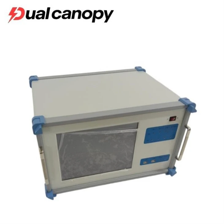

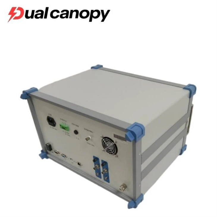

Dual Canopy Mechanic Electrical Engineering Co., Ltd. is one of the leading manufacturers and suppliers of Partial Discharge Tester in China. Please feel free to wholesale discount products for sale here and get quotation from our factory. Customized orders are welcome.
Products Description

The Partial Discharge (PD) Tester is a highly sensitive diagnostic instrument designed to detect and analyze partial discharge activity within high-voltage (HV) insulation systems. Partial discharge is a localized electrical discharge that only partially bridges the insulation between conductors, and it is a primary indicator of insulation degradation.
Unlike Hipot testers that apply high voltage to test for breakdown (a destructive "go/no-go" test), PD testers operate at normal or slightly elevated operating voltages to detect incipient faults without damaging the insulation. This makes PD testing a cornerstone of Condition-Based Maintenance (CBM) for critical power assets.
Our PD tester supports multiple detection technologies, including Ultra-High Frequency (UHF), Transient Earth Voltage (TEV), Ultrasonic, and High-Frequency Current Transformer (HFCT) methods. It enables engineers to identify the type, severity, and location of insulation defects in GIS, power cables, transformers, and switchgear, facilitating timely intervention before catastrophic failure occurs.
Technical Parameter
|
Technical characteristics |
|
|
Number of interfaces |
Free-running 4 interfaces |
|
Sampling rate |
1M. 5M. 10M selected |
|
Sampling accuracy |
12bit |
|
Range changing |
-40dB, -20dB, 0dB, 20dB, 40dB ,60dB, totally 6 types |
|
Measurement frequency range |
3db bandwidth 10kHz~1MHz |
|
Digital filtering |
10kHz~1MHz freely selected |
|
Program controlled filter subsection |
Low frequency: 10kHz,20kHz,40kHz,80kHz High frequency: 100kHz,200kHz,300kHz,400kHz |
|
Nonlinear error in the range |
10% |
|
Measurement range |
0.1pC~100,000pC |
|
Sensibility |
0.1pC |
|
Capacity range of the measured product |
6pF~250µF |
|
Frequency range of test power |
50~500Hz |
|
Display |
|
|
Display screen |
12'' TFT true color touchable LCD screen |
|
Resolution |
1024×768 |
|
Interface |
|
|
USB |
3 types, use of external mouse, keyboard or other USB devices. |
|
Power mode |
AC 220V; Frequency 50Hz; Power 300W |
|
Electric signal interface |
4 BNC interfaces, use of signal input. |
|
Optical signal interface |
4 types, use of signal input |
|
Network interface |
1 type |
|
Landing button |
External landing |
|
General instruction |
|
|
CPU |
Basic frequency 1.60GHz |
|
Ram |
2.0GB |
|
Hard disk |
128GB SSD |
|
System |
Windows Xp |
|
Operating environment |
Environment ambient: -10~45 Humidity: ≤95%RH |
|
Size |
Length×width×height: 474mm × 288mm × 370mm |
|
Weight |
15.8kg |
What are the application scenarios for this device?
1. GIS (Gas-Insulated Switchgear) Inspection
Internal Defect Diagnosis: Utilizes **UHF (Ultra-High Frequency)** sensors to detect free-moving metal particles, insulator support defects, and gas-gap discharges within the GIS.
Live-Line Inspection: Employs **TEV (Transient Earth Voltage)** sensors to perform rapid scans on the external surface of the GIS, assessing the severity of internal discharges without the need for power outages or enclosure opening.
Acoustic Localization: Integrates ultrasonic sensors to pinpoint the location of discharge sources by analyzing the time difference in acoustic wave propagation.
2. High-Voltage Power Cable Monitoring
Cable Body and Joints: Utilizes **HFCT (High-Frequency Current Transformers)** installed on the cable's grounded shielding layer to detect insulation aging in the cable body and defects in joint fabrication.
Long-Distance Localization: Precisely calculates the distance to a fault point by analyzing the propagation time difference of discharge pulses within the cable (based on the TDR principle), achieving localization accuracy down to the meter level.
3. Power Transformer Diagnosis
Internal Discharge Detection: Uses HFCTs to detect current flow at the ungrounded side of the transformer's neutral point, identifying inter-turn short circuits in windings, multi-point grounding in the core, and floating potential discharges.
Integrated Insulation Oil Analysis: Combines with Dissolved Gas Analysis (DGA) to further confirm the nature of the discharge (e.g., whether the discharge type indicates a thermal fault or an electrical fault).
4. High-Voltage Switchgear and Busbar Systems
Surface Contamination and Moisture: Employs TEV sensors to detect surface discharges within the switchgear caused by surface contamination or moisture ingress.
Precursors to Contact Overheating: While primarily designed to detect discharges, severe contact anomalies can also generate specific high-frequency signals, serving as an auxiliary diagnostic tool.
5. Rotating Machinery (Generators/Motors)
Stator Winding Insulation: Utilizes coupling capacitors or HFCTs installed at the motor's end windings to detect slot discharges in the stator windings and assess the degree of insulation aging.
1. Solution Customization: We recommend appropriate sensor combinations and main unit configurations based on the client's equipment type (GIS model, cable length, transformer capacity) and inspection objectives (routine inspection, fault localization, or online monitoring).
2. Technical Feasibility Analysis: For complex environments (such as substations with high electromagnetic interference), we provide on-site surveys to assess the feasibility of the inspection.
3. Standards Consultation: We address questions regarding the application of relevant standards, such as IEC 60270 (Partial Discharge Measurements) and DL/T 911.
4. Demonstrations and Trials: We offer equipment demonstrations to illustrate how to identify typical defects using PRPD patterns.

FAQ
Q1: What is the difference between partial discharge testing and withstand voltage testing? Can one substitute for the other?
A: They cannot substitute for one another; rather, they are complementary.
Withstand voltage testing is a "destructive" or "limit" test; by applying a voltage higher than the operating voltage, it verifies whether the insulation breaks down. It can only tell you if the insulation is "already failed."
Partial discharge testing is a "non-destructive" or "diagnostic" test; it detects faint discharge signals at the operating voltage level. It can tell you if the insulation is "deteriorating" or if latent defects exist.
Recommendation: Withstand voltage testing is required for the acceptance of new equipment; for the maintenance of in-service equipment, partial discharge testing is the preferred choice, as it can detect early-stage defects that withstand voltage testing cannot identify, without causing damage to the insulation.
Q2: What is a PRPD pattern? What is its utility?
A: PRPD (Phase-Resolved Partial Discharge) is a distribution map plotting partial discharge amplitude against the voltage phase angle. It acts as a "fingerprint" for specific faults.
Internal Void Discharge: Typically presents a "rabbit-ear" shaped distribution, appearing near the voltage peaks.
Surface Discharge: Exhibits a broader distribution, often appearing near the voltage zero-crossing regions.
Floating Electrode Discharge: The pattern presents an irregular, scattered "finger-like" distribution.
By analyzing PRPD patterns, experts can identify the type and severity of the insulation defect.
Q3: Is it possible to detect partial discharge inside a GIS without interrupting power supply?
A: Yes, it is. This is a major advantage of PD detection.
UHF Method: By utilizing UHF sensors mounted on the GIS enclosure (or sensors temporarily installed at inspection windows or waveguides), internal discharges can be detected while the equipment remains energized.
TEV Method: By measuring Transient Earth Voltage on the surface of the GIS enclosure, detection can similarly be performed under energized conditions.
Ultrasonic Method: By receiving acoustic signals on the surface of the GIS enclosure, detection can also be performed while the equipment remains energized.
Hot Tags: Partial Discharge Tester, China Partial Discharge Tester manufacturers, suppliers, factory, transformer partial discharge test set, online partial discharge meter, tev partial discharge test


