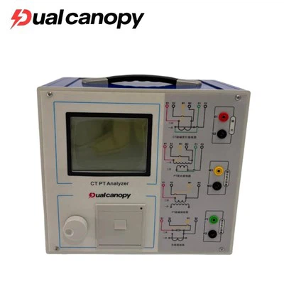
A Contact Resistance Tester - also commonly referred to as a Micro-Ohmmeter, Low-Resistance Ohmmeter (LROM), or Ductor Tester - is a precision electrical instrument specifically designed to measure very low resistance values, typically in the range of micro-ohms (μΩ) to milli-ohms (mΩ). It is primarily used to assess the quality and integrity of electrical contact joints, connector terminations, bus bar connections, cable joints, switchgear contacts, and welded or bolted current-carrying connections.
The fundamental importance of contact resistance measurement lies in Joule's Law (P = I²R). Even a very small resistance value - seemingly insignificant at low current levels - can generate substantial heat energy when carrying high load currents. For example, a contact resistance of just 100 μΩ carrying 1,000A of load current will dissipate 100 watts of heat energy continuously at that connection point, leading to progressive thermal damage to insulation, connectors, and surrounding components.
Contact Resistance Testers are indispensable tools in power utility maintenance, transformer manufacturing, circuit breaker testing, railway infrastructure maintenance, aerospace quality control, and industrial switchgear commissioning - any application where the resistance of current-carrying joints must be verified to be below a specified maximum threshold.
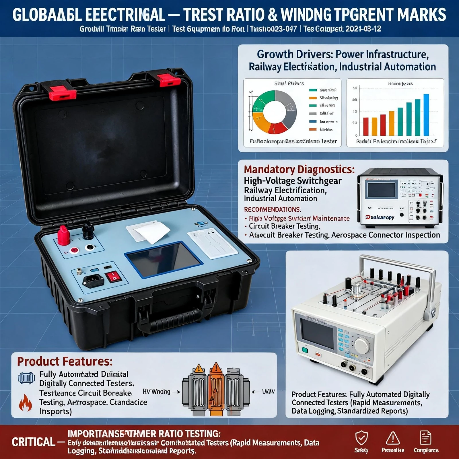
Contact resistance testers operate on the Kelvin Four-Wire (4-wire) measurement principle, also known as the Kelvin sensing method or four-terminal measurement. This technique is essential for accurate low-resistance measurements because it eliminates the influence of lead resistance and contact resistance of the measurement connections themselves - errors that would be unacceptably large relative to the micro-ohm values being measured.
How the Four-Wire Method Works:
Current Leads (C1, C2): A precisely controlled DC test current (typically ranging from 10A to 600A depending on the instrument model) is injected through the component under test using two dedicated current-carrying leads.
Voltage Leads (P1, P2): Two separate, high-impedance voltage sensing leads are connected directly across the component under test (inside the current lead connection points). These leads carry virtually no current.
Calculation: The instrument measures the voltage drop across the component (V) and the test current (I) simultaneously, then calculates resistance using Ohm's Law: R = V / I. Because the voltage leads carry negligible current, their resistance does not affect the measurement result.
Why High Test Current Is Important: Using a high test current (100A or above) is critical for obtaining accurate contact resistance readings on oxidized or contaminated contact surfaces. Low test currents can be fooled by thin oxide films that appear to have acceptable resistance but will break down under actual load current conditions.