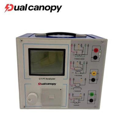
Short-circuit one side of the transformer (usually the low-voltage side), and apply the rated frequency AC voltage to the other side of the winding (with the tap position at the rated voltage). This will make the current in the transformer winding reach the rated value. Measure the applied voltage and power, and convert them to the values at 75℃. This power is the load loss of the transformer, and the measured voltage is the impedance voltage. This test is called the short-circuit test of the transformer.
The actual load loss of a transformer is actually the copper loss, which is the heat loss generated when current passes through the transformer's windings. It will directly affect the temperature rise of the windings and other parts. Therefore, the magnitude of the load loss has a significant impact on the economic operation of the transformer.
Impedance voltage (short-circuit voltage) is the voltage applied during the short-circuit test. It is one of the basic conditions for the parallel operation of transformers. When a short circuit occurs in the system, the short-circuit current of the transformer and the resulting force depend on the magnitude of the impedance voltage. When the load of the transformer changes significantly during operation, the impedance voltage directly affects the network fluctuations.
The short-circuit test of the transformer is not only conducted by the manufacturer, but also carried out by the operating unit during major overhauls or after accidents, as well as when several transformers need to be operated in parallel.
Transformer Comprehensive Characteristic Testing Station
Objective of the experiment
Through short-circuit tests, it is possible to detect whether the transformer has the following defects.
(1) In the various movable parts of the transformer (shielding, clamping rings, capacitor rings, yoke beam plates, etc.) and the oil tank wall, excessive additional losses or excessive local heating due to leakage magnetic flux have reached values that are not allowable.
(2) The top cover of the transformer oil tank and the accessory of the outgoing line terminals are overheating, and the additional losses have increased.
(3) The additional losses of the multi-layer spiral low-voltage winding are significantly increased due to the short circuit of the parallel conductors in the special interlacing positions within the winding, or because of the incorrect interlacing of the conductors during the winding manufacturing process.
From the above analysis, it can be seen that the load loss and impedance voltage are the main parameters during the operation of the transformer. Therefore, the short-circuit test is very important and necessary.
Measurement method
Usually, the three-phase power supply method is used on-site for short-circuit characteristic tests.
During the test, connect all the test instruments and meters as per the diagram. Connect the three-phase power supply to the three-phase voltage regulator and to the high-voltage side of the tested transformer. Short-circuit the low-voltage side. After checking that the wiring is correct, gradually increase the voltage and observe the indications on the meters. When everything is normal, raise the voltage to the rated value and read the indications on each meter. If there is an imbalance in the three-phase current, use the arithmetic average of the current meter indications as the reference.
Test Requirements
(1) Temperature correction for tests. Short-circuit tests, like the measurement of DC resistance, are also affected by temperature. Before the test, the temperature should be recorded, and the measurement results should be converted to the reference temperature. Generally, the data is converted to the value at 75℃.
(2) Current correction for tests. During short-circuit tests, a power supply with a larger capacity is required, typically accounting for 5% to 20% of the capacity of the tested transformer. If the site is restricted by conditions and cannot conduct the test at the rated current, it is allowed to conduct the test at a reduced current. However, it should not be lower than 25%. The test results should be converted to the load loss results at the rated current according to the formula.
Notes for Attention
(1) When measuring instruments need to be measured through transformers, the polarity of the current transformer should be correct, and the polarity of the voltmeter should also be correct.
(2) Since the DC resistance of the transformer is very low, the cross-sectional area of the short-circuit line should be large and the connection should be good to reduce the contact resistance.
(3) During the short-circuit test, if the measured loss is relatively small, the loss of the instrument should be taken into account and corrected.
(4) The short-circuit test is usually conducted in a cold environment. For transformers that have just been taken out of operation, the test can only be carried out when the winding temperature drops to the oil temperature. The test duration should be short and the readings should be taken quickly to avoid overheating of the coils, which could affect the accuracy.
(5) If there is a current transformer inside the transformer's bushing, its secondary side should be short-circuited.
Analysis and judgment of the test results
(1) The short-circuit test mainly measures two parameters: load loss and impedance voltage. According to the provisions of GB1094: the allowable deviation for load loss is 10%; the allowable deviation for impedance voltage is 10%.
(2) The impedance voltage is related to the geometric dimensions of the winding. It is directly proportional to the frequency; directly proportional to the ampere-turns per column of the transformer; directly proportional to the total leakage magnetic area; inversely proportional to the voltage per turn and the height of the winding. The magnitude of the impedance voltage is also related to the arrangement of the windings. Therefore, when the measured data is inaccurate, one can look for the problem from these aspects.
(3) The load loss consists of resistance loss and additional loss. Usually, the additional loss is the main component. The reason for this is that during manufacturing, there are short circuits between the strands of the winding and short circuits between the phases.