The significance of measuring the grounding conduction resistance
According to safety regulations (such as power safety regulations, national standard GB/T), the metal enclosures and frameworks of all electrical equipment must be reliably grounded. The purpose of measuring the grounding conduction resistance is:
Verify the reliability of the secure connection: Ensure that the grounding wire is not broken, disconnected, severely corroded or has loose connections.
Preventing electric shock accidents: A low-resistance grounding path can provide a low-impedance discharge path for the fault current, prompting the protective devices (such as circuit breakers, fuses) on the line to act quickly and cut off the power supply.
Ensure the normal operation of equipment: For lightning protection grounding and working grounding, good grounding is the foundation for the stable operation of the system.
Compliance with regulations and testing requirements: This is a mandatory item for regular safety inspections in the fields of power systems, construction engineering, industrial production, etc.
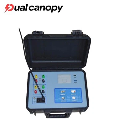
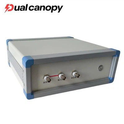
Grounding Conductor Downlead Conductivity Resistance Tester
Application scenarios of the grounding lead-down conductor conduction resistance tester
Power system: Measurement of grounding resistances for transformers, switch cabinets, lightning arresters, and power line towers within the substation.
Construction project: Conductivity tests for the electrical potential connections of distribution boxes, mechanical and electrical equipment, elevators, metal doors and windows within the building.
Industrial production: Inspection of protective grounding for machine tools, control cabinets, and production line equipment in the factory.
Communication system: Grounding detection for communication base stations and equipment in the machine room.
Lightning protection inspection: Measurement of connection resistance between lightning rods, down conductors and grounding grid.
Test operation steps for the grounding lead-down conductor conduction resistance tester, taking the measurement of equipment grounding conductivity as an example:
Preparatory work:
Instrument calibration and self-check.
Make sure the equipment being tested is powered off.
Clean the grounding terminals of the tested equipment and the grounding connection points of the earth to ensure good contact.
Connection:
Connect the voltage measurement lines (P1, P2) of the instrument to the same pair of points, but on the inner side of the current lines. For the conduction test, the four-wire direct connection method is usually adopted, where C1-P1 is connected to the equipment end, and C2-P2 is connected to the grounding end.
Connect the current output lines (C1, C2) of the instrument to the grounding terminals (E) of the device and the distant grounding electrode (C).
Measurement:
Turn on the machine and select the appropriate test current (such as 10A, 25A, etc. A larger test current is helpful in detecting contact problems).
Start the test. The grounding lead-down line conduction resistance tester will automatically output current and calculate and display the resistance value.
Once the reading stabilizes, record the result.
Judgment and Record:
Based on the relevant standards (typically requiring ≤ 0.5Ω), determine whether the resistance value is qualified.
Record the test data, test location, environmental conditions and test personnel.
Notes for Attention
Safety first: Ensure that the equipment has been completely powered off and follow the electrical safety operating procedures.
Correct wiring: Make sure the test leads are securely and correctly connected. Poor contact can lead to inaccurate measurements or even damage to the instrument.
Test line separation: When measuring a large grounding grid, the voltage line and the current line should be kept as far apart as possible to avoid entanglement, in order to reduce mutual inductance interference.
Environmental interference: In a strong electromagnetic field environment, it is recommended to choose the frequency conversion models with anti-interference capabilities.
Battery status: When testing high current, make sure the instrument battery is fully charged.