

The purpose of the 25kV power frequency withstand voltage test: To verify the main insulation strength of newly installed (commissioning) or operating (preventive) cables. It simulates the overvoltage that the cables may encounter during operation to detect insulation defects (such as impurities, air gaps, damage, etc.), ensuring the safety and reliability of the power grid.
Standard basis: Primarily follows national standard GB/T 3048.8 and power industry standard DL/T 474.4. The test voltage is generally several times the cable's rated voltage (such as 8.7/10kV, 26/35kV) (e.g., 2-3 times U0), and the test duration is 5-60 minutes (depending on the standard requirements).
Power frequency: Refers to the frequency of the test voltage being 50Hz (in China), which is the same as the actual working frequency of the power grid. This is the most direct, most rigorous, and also the most authoritative method for testing insulation.
A 25kV power frequency withstand voltage test system usually consists of:
Main core equipment:
Test transformer: This device raises the mains voltage (such as 380V/220V) to the required 25kV high voltage. The capacity is usually 5kVA, 10kVA, 20kVA or higher, depending on the length and capacitance of the tested cable.
Reducer/Control Panel: It is used to smoothly and continuously adjust the input voltage, thereby precisely controlling the high-voltage output. Modern equipment mostly uses electric reducers or induction reducers, while older equipment might use autotransformer reducers.
Power frequency withstand voltage test device
High-voltage measurement system: Used for accurately measuring the high voltage applied to the cable. Common methods include:
High-voltage pressure reducer (resistor or capacitor type) + low-voltage instrument.
Measure at the low-voltage side of the test transformer and convert using the transformation ratio (this requires calibration).
Safety protection system: It includes overcurrent protection, overvoltage protection, zero-position startup, emergency stop, safety door interlock, etc., to ensure the safety of personnel and equipment.
Auxiliary and accessory equipment:
Protection resistor: Connected in series in the high-voltage circuit, it is used to limit the short-circuit current when the test sample breaks down, protecting the transformer and measurement equipment.
High-voltage filter capacitor: Used to improve the voltage waveform, especially when testing long cables (with a large capacitive load), to prevent waveform distortion and spikes.
Compensation reactor: For long-distance cables (with large capacitance), capacitive current will cause a significant increase in the transformer's capacity requirement. Parallel adjustable reactors for resonance compensation can significantly reduce the capacity of the required test transformer. This is the core idea of the current mainstream variable-frequency series-resonance withstand voltage test system (although it is called "variable frequency", its output is still 50Hz industrial frequency).
Partial discharge detection system: During high-end tests, partial discharge detection is carried out simultaneously, enabling the identification of minor defects within the insulation during the withstand voltage process.
A brief description of the power frequency withstand voltage test process
Preparation: Unfasten both ends of the tested cable, isolate them, clean the connectors. Set up the test equipment, connect the grounding wire, and establish a safety fence.
Connection: Connect the high-voltage output of the test equipment to one phase of the cable, and ensure reliable grounding for the other phases, the shielding layer, and the armor layer.
Parameter settings: In the control box, set the target voltage, withstand time, protection limit value, etc.
Boosting: Start the equipment, automatically or manually adjust the frequency to find the resonance point, and then increase the voltage to the predetermined test voltage.
Withstand Voltage: Maintain the specified voltage for a given period of time (e.g. 5 minutes), and closely monitor whether the voltage and current remain stable.
Evaluation: If there is no breakdown, no flashover, and no abnormal increase in current during the withstand voltage test, then it is considered that the cable of this phase has passed the test.
Phase switching: After reducing the voltage, discharging, and grounding, switch to the test phase and repeat steps 2-6 until all three phases are completed.
Safety Precautions for Power Frequency Withstand Voltage Test
The power safety regulations must be strictly followed. Clearly marked safety warning zones should be set up, and dedicated personnel should be assigned for supervision.
Before and after the test, the cables and the test equipment must be fully discharged and grounded.
Operators must undergo professional training and be familiar with the equipment and the testing procedures.
Take note of the influence of the test environment (humidity, contamination), and take corresponding measures if necessary.
Composition And Test Process Of 25kV Power-Frequency Withstand Voltage Test Equipment
Popular Products

Open Flash Point Tester
Product Introduction Features: Fully automatic flash point tester, with touch screen instead of keyboard operation.

Capacitance Test
Products Description This 50kVA single phase pole mounted transformer is exported to Canada inJuly,2024.The rated

TTR Transformer Turns Ratio Tester
Products Description The ZS6810A / ZS6810E transformer ratio tester is mainly used for measuring the turns ratio or

Single-phase relay protection tester
The single-phase relay protection tester is a new type of intelligent test instrument, primarily used to calibrate

Sweep Frequency Response Analysers
Products Description Overview The Transformer winding deformation tester transformer winding deformation tester is used
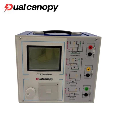
CT PT Excitation Characteristic Analyzer
Products Description The transformer comprehensive measuring instrument is an electronic device used for on-site